IEC Master
PRODUCTS AND SOLUTIONS FOR MONITORING AND CONTROL IN THE ENERGETICS

IEC Master
The IEC Master application is primarily used for testing and verification of slave devices that communicate IEC 60870-5-101 and IEC 60870-5-104 protocols.
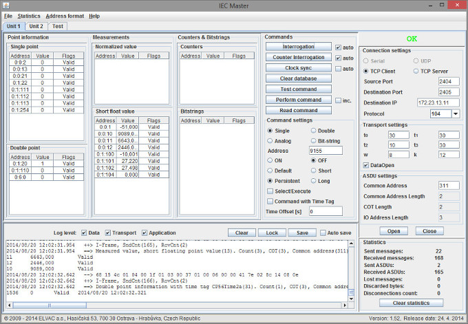
The serial link, TCP (client and server) and UDP protocols can be used for data transfer. In the application configuration, only a few communication parameters need to be set and the application is ready for use. The database of signals and measurements is created dynamically, so it is not necessary to define it in advance. The application provides signal states and measurement values (normalized values and decimals) including quality attributes. It is possible to send to the slave device a total (general) query, time synchronization, test command, one-bit and two-bit command both with and without time. A listing of the ongoing communication is also displayed for diagnostic purposes. For automated testing, the application provides an interface for running test scripts.
Brief characteristics
- communication protocols IEC 60870-5-101 and IEC 60870-5-104,
- data transmission via serial link, TCP (client and server) and UDP,
- display of current signal states and measurement values,
- generation of general queries, time synchronisation, commands,
- recording and storing ongoing communication,
- displaying statistics,
- easy configuration of the application,
- possibility to save and retrieve the configuration,
- demo mode for testing.

Communication log
Ongoing communication can be logged. The user can choose the logging level. The first level logs the raw data that is sent/arrived to/from the selected communication interface. In the second level, the passing data is processed at the link/transport layer (establishing and maintaining connections, …). The third level logs application data (signal values, measurements, …). The communication log can be saved for later analysis upon user request or automatically.
Test interface
The IEC Master application enables automated testing of the inputs and outputs of slave devices. It is possible to define a scenario with actions (control of outputs) and reactions to them (desired signal states). Furthermore, a time limit for the response is defined (the response must occur within a predefined time). The output of the test is then a report that contains a list of changes that have occurred on the monitored device, including information on whether or not the change was expected. After the test is completed, a statistic of the number of possible erroneous (unexpected) signal states is also displayed. The incoming measurement will only trigger a warning.